I’ve had the chance to build a few AMD-based Supermicro boxes over the years. SuperMicro makes server cases, motherboards, and other datacenter equipment. Because they provide both cases and motherboards, they’ve standardized a front panel header that works, I presume, with all of their products. I have only ever used alternative ATX rackmount cases, so I have been left to wire up the front panel headers by hand.
Unfortunately, the pin diagram for the SuperMicro front panel header on some of their boards isn’t what I’ve come to expect building boxes over the years. Most motherboards will declare Signal+ and Signal- for all things that are relevant on the front panel, but the front-panel header on the H11SSL SuperMicro boards looks like this:
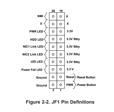
The power and reset buttons are labeled as expected, Power+ and a nearby ground. The LEDs however list each LED with an adjacent 3.3V powered pin. Typically I would expect to see LED+ and LED- or LED and ground, so for a while I was avoiding plugging in the LEDs to avoid frying any case panels or motherboard parts.
A short time ago, I looked for pinouts for other SuperMicro boards (since the connector is standard), and I found the explanation. Here’s a description of the C7z97 motherboard header pinout:
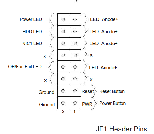
This makes it more explicit. Each LED listed is LED- while the 3.3V pins are intended to be LED+.
This article also backs up my findings: https://www.unixgr.com/pinout-for-supermicro-fp836-front-panel-connector/
To switch naming conventions within a diagram seems odd, but now it’s clear. Maybe someone else will find this useful.